Blower motor, resistor: how it works, symptoms, problems, testing
By Vlad Samarin Updated: May 20, 2023
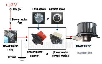
The motor that runs the fan in the heating and air conditioning system in a car is called a blower motor. It's located inside the dash, often on the opposite side of the steering wheel or inside the engine compartment on the firewall. A blower motor resistor or a blower motor control module is the part that controls the speed of the blower motor.
 How the speed of the blower motor is controlled. See also:
 Photo of a Mazda blower motor resistor
Honda blower motor control module.
Cars with an automatic climate control system and vehicles where the blower speed can be adjusted gradually are equipped with an electronic blower motor control module, see the photo.
In most modern cars, the blower motor resistor or the control module are installed inside one of the ducts in the HVAC system, close to the blower motor. This is done, so the resistor or a control module is cooled down by passing air. In some older cars, a blower motor resistor was installed on the firewall with access from under the hood.
Blower motor resistor / control module problems
Problems with a blower motor resistor are common in many cars. The most common symptom of a failed blower motor resistor is when the heater fan only runs at the highest speed setting (4 or 5) and doesn't work at low speeds. In some cars, a failed blower motor resistor can cause a heater fan to stop working completely.In most cases, a blower motor resistor fails due to corrosion or overheating. Sometimes, the mechanical resistance to the motor rotation causes an excessive electric current that can overheat and prematurely damage the blower motor resistor. For example, this happens when the fan blade is jammed by a foreign object or when the motor bearings are worn out and it doesn't spin freely.
Problems with a blower motor control module are less frequent, but it fails for the same reason: due to corrosion or overheating when the motor is jammed or shorted. In most cases when a blower control module fails, the blower motor doesn't work at all. In some cars (e.g., older GM trucks), a failed blower control module or processor can cause the blower motor to continue running even with the ignition OFF.
How is the blower motor resistor diagnosed?
Diagnostic procedures vary. Often a visual inspection of the resistor reveals the problem. For example, as you can see in this photo, the blower motor resistor in this Ford Escape has failed due to corrosion.If the resistor shows no visual damage, the resistance between terminals must be checked and compared to specifications. If the resistance is out of specs, the resistor must be replaced.
For example, in this photo we measured the resistance of this blower motor resistor. According to the service manual, it must be around 4-5 ohms. In our case the ohmmeter shows open circuit, which means the resistor has failed.
Sometimes, a blower motor resistor might fail due to problems with the blower motor itself. This means after replacing the blower motor resistor, check if the blower motor runs freely and doesn't make any noise. We have seen instances where a worn-out blower motor causes a recently replaced resistor to fail again. For example, this issue was common in older Chrysler and Dodge minivans. In this case, the blower motor must also be replaced. One of the symptoms of a worn out blower motor is that it can intermittently produce a loud screeching noise when running.
How to test the blower motor?
If the blower motor doesn't work at all, the blower motor itself must be tested first. Typically it's done by measuring the voltage at the blower motor connector when it's turned on. If there is a voltage at the motor (at least 4-6 Volt at low speed and 12 Volt at high speed), but the motor doesn't run, the motor is bad or jammed. Testing the voltage at the blower motor. If there is a voltage at the motor (at least 4-6 Volt at low speed and 12 Volt at high speed), but the motor doesn't run, the motor is bad.
Things like leaves, twigs, nuts, pieces of a ripped cabin filter can jam the blade of the blower motor. This happens often in many cars.
If there is no voltage at the motor, the entire blower motor circuit must be tested, starting from the fuse. Read: How to Check a Fuse in a Car.
If the blower motor is bad, it will need to be replaced. The blower motor replacement costs from $320 to $650, depending on the car. In many cars it's fairly easy; the blower motor is located behind the glove box and held by 3-4 screws. In others, it might be located inside the dash (e.g. Mazda 5) which makes replacement difficult.
If you need a proper diagnostic procedure, we posted a list of websites that offer paid access to service manuals for different cars at the bottom of this article: Check Engine Light: What to check first, repair options.
How is the blower motor control module tested?
Mechanics at a dealership can diagnose the HVAC system with a scan tool. If the scan tool is not available, in many cars with an automatic climate control system there is a self-testing or diagnostic mode.Advertisement
Another way is to check the voltage at the blower motor, the blower motor control module and other parts of the circuit according to the service manual. For example, in the mentioned 2009 Honda Accord, the + 12V power is supplied directly to the blower motor through the fuse and then through the relay. The blower motor control module (Honda calls it Power Transistor) supplies the ground. The power transistor has 4 wires: two come from the climate control system control unit, one is the ground, one goes to the negative terminal of the blower motor. The service manual advises measuring the voltage at the blower motor, then if not OK, at the power transistor and so on.
A failed power transistor was a fairly common cause for not working blower motor in some Honda and Acura vehicles. For example, the Honda bulletin 03-048 described a problem where the blower motor for the rear HVAC system in the 2003 Pilot would not work at all speeds. The bulletin recommends replacing the rear power transistor as a solution.
BMW calls the blower motor control module a Final Stage Unit, which is also fairly common to fail. Sometimes it doesn't fail completely, but causes the blower motor to stop working intermittently or run at various speeds. See these YouTube videos for more info.
In some GM trucks, a blower motor control module failure can cause the front blower motor to stop working or run after the vehicle has been shut off. The GM bulletin 06-01-39-002C describes this problem that happens in cold weather. The bulletin advises replacing the blower motor control module. GM calls it Linear Power Module (LPM). Watch these YouTube videos for more info.
Repair options
Your local mechanic or any small repair shop should be able to diagnose the problem. Of course, the quickest way is to make an appointment with your dealer. Many dealers have the part in stock. The blower motor resistor or control module replacement is not very expensive.For example, one of our colleagues had a problem with his 2011 Ford Escape: the fan only worked at the speed 4. The Ford dealership charged $60 to diagnose and $152 to replace the resistor. When the same problem occurred two years later, our colleague ordered the part online for $25, found the DIY Youtube video describing the repair and replaced it within 25 minutes.
 In the 2008-2011 Ford Escape / Mazda Tribute, the blower motor resistor is located on top of the HVAC unit, behind the glove box.
In the 2008-2011 Ford F150, the blower motor resistor is also located behind the glove box, but is installed on the right side of the plastic air duct. This thread at f150online.com shows where the resistor is located.
The author of this blog shared his experience of replacing the blower motor resistor in Jeep Liberty. In some older cars and trucks, the blower motor resistor is installed on the firewall, with access from under the hood.
How the blower motor resistor works
 Typical blower resistor diagram
In this diagram, the fan switch is set to the speed "1", so the blower motor current is reduced by three resistors (R2 + R3 + R4) connected in series. The current flow is shown in blue and red.
In the setting "2", there are two resistors connected in series, and in "3", there is only one resistor.
Adding resistance to the electric circuit reduces the current in the circuit. When several resistors are connected in series, the total resistance increases and is equal to the sum of individual resistances.
Read Next:
How to Check a Fuse in a Car?
How to Check a Fuse in a Car?


